The following are online links for manuals and tutorials for CeX3D Inverse:
This document is also available in PDF format:
The following sections constitute the user's manual for the
graphical user interface (GUI) version of CeX3D Inverse.
This manual covers both CeX3D Inverse NCU and CeX3D Inverse Pro.
Introduction
CeX3D Inverse is a computer program for automatically turning ordinary photographs into digital 3D models. This is possible for many everyday photos, provided that enough photos are taken from suitable angles of the same scene or object. The scene or object must be static, i.e. not moving. At least two, though preferably three or more pictures are necessary for this. The pictures must also be sharp, i.e. not too blurry, for this to work properly.
Certain kinds of objects are, however, not suitable for automatic reconstruction. Such objects include: fluffy objects like clouds, hair and grass; transparent objects and mirrors as well as objects that are too shiny; very small or thin objects, such as wires, antennas, grids and lattices; objects with a smooth surface that are of the same colour all over and has no texture at all. If such objects occur in the photos, they will likely not be reconstructed very well and if there are too many of such objects, it may completely prevent successful 3D reconstruction.
The DOs and DONTs Tutorial is strongly recommended for examples on how to take suitable photographs for 3D reconstruction.
The quality of the reconstruction will gradually improve over time
with new versions of CeX3D Inverse
and it will become possible to handle more and more challenging
photographs. Hence, what is not possible to reconstruct today may
become possible to reconstruct in a later version of CeX3D Inverse,
using the same photographs.
General Operation of CeX3D Inverse
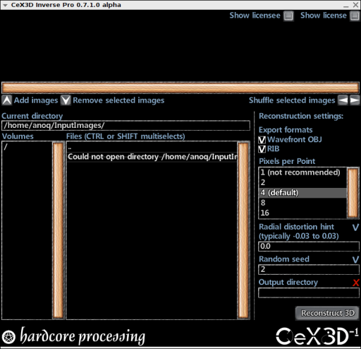
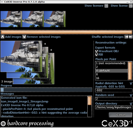
Performing 3D reconstruction from photos with CeX3D Inverse is done by starting CeX3D Inverse and selecting a set of pictures for input. Some options for specifying how the reconstruction is done and how CeX3D Inverse operates can also be specified. This is done in the graphical user interface which typically looks as follows when started for the first time:
CeX3D Inverse is started by executing the command cex3dinversegui, e.g. in a terminal on Linux systems or a DOS prompt on Windows systems or by setting up an icon to call this command. This command can only be called directly if it was installed into some directory that the PATH environment variable points to. Alternatively, you will have to include the full path of where CeX3D Inverse is installed when starting it, e.g. by this command:
/usr/local/bin/cex3dinversegui
on Linux, if CeX3D Inverse was installed with /usr/local/ as root directory, or:
C:\Program Files\Hardcore Processing\CeX3D Inverse\bin\cex3dinversegui
on Windows, if CeX3D Inverse was installed with C:
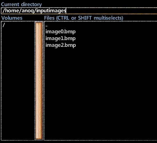
As an example, reconstructing a 3D model from three pictures in files named 'image0.bmp', 'image1.bmp' and 'image2.bmp' can be done by going to the directory where those images are located, either by typing in the Current directory field:
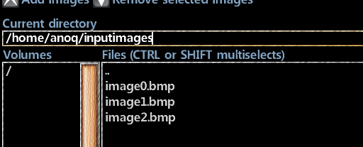
Or by browsing files in the Files listbox, where double-clicking on a directory name changes the Current directory into that directory and double-clicking on the two dots ".." changes to the parent of the current directory.
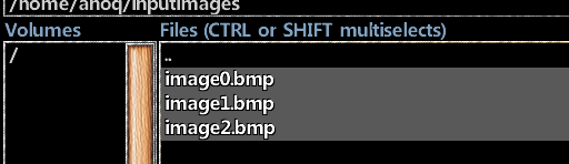
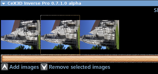
When the desired directory has been found, the image files may be selected in the Files listbox using the mouse, where holding down either the CTRL key or the SHIFT key can be used for selecting multiple files:
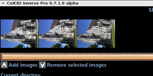
To add the selected images to the image sequence used for 3D reconstruction, press the Add images button:

The added images will appear in the image sequence used for 3D reconstruction:
The following image formats are supported for input on Linux (via the SDL_image library): BMP, GIF, JPEG, LBM, PCX, PNG, PNM, TGA, TIFF, WEBP, XCF, XPM and XV. On Windows, however, only BMP format is currently supported; we expect this to improve one way or another in coming versions.
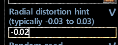
It is possible to specify a hint of the typical radial distortion in the images. This was strongly recommended in versions 0.7.0.0 and 0.7.1.0 but has become less important starting from version 0.7.2.0 of CeX3D Inverse. This is described in more detail for the reconstruction setting 'Radial Distortion Hint'. Cameras typically have a distortion that corresponds to a radial distortion hint of between -0.03 and 0.03. Hence, e.g. -0.02 could be a good hint value. Specifying this is done by entering the desired value in the field Radial distortion hint:
The radial distortion, however, depend on which camera is used (particularly its lens), on how its zoom settings are as well as slightly on focus settings; using autofocus makes this somewhat uncontrollable. Typically, when the camera is zoomed out, the distortion is more negative, e.g. -0.02 or lower. When zooming in, the distortion gets closer to zero or even becomes positive, depending on the lens and camera.
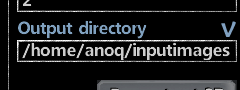
When the 3D reconstruction is performed, the generated models are placed in the directory specified for Output directory:
If the output directory was invalid earlier on when the Add images button was pressed, the directory that the images were added from will be automatically filled in here.
Performing the 3D reconstruction is done by pressing the button Reconstruct 3D:

During the reconstruction, an image icon of the images, a progress bar and a listbox with messages are displayed:
The reconstruction is carried out by the command line version of CeX3D Inverse running as a separate process and the messages shown are from the output of the command line version. It is possible to cancel the reconstruction, by pressing the Cancel button (this was not guaranteed to work in early CeX3D Inverse versions but works reliably from version 0.7.2.0):

Currently, the most frequent point of failure in the reconstruction is the radial distortion estimation and for this reason, you may want to try the reconstruction with several different values for Radial distortion hint. The estimated radial distortions are shown during reconstruction:
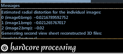
This may give you an idea of how the actual radial distortion is, by comparing the estimated distortion values with the quality of the reconstructed 3D model: when you get a good 3D model, the estimated radial distortions are likely closer to the truth than when you get a bad model.
When the reconstruction is complete, the Cancel button changes to Done and you can click the Done button to prepare for a new reconstruction:
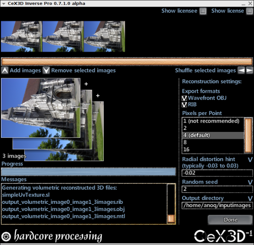
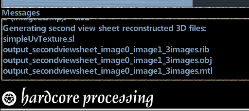
CeX3D Inverse currently generates two different kinds of 3D model files: a low-resolution model whose file name normally starts with 'output_secondviewsheet_' and a high-resolution model whose file name normally starts with 'output_volume_'.
Generating the high-resolution model is currently very resource intensive, taking time and using lots of memory, and it may fail. The resolution of the high-resolution model can be controlled by the setting Pixels per Point and also depends on the resolution of the input images. The default value is 4 and higher values give a lower resolution model. To get a model at a lower resolution for the above example, try setting Pixels per Point to 8:
If your input images have a fairly low resolution (e.g. less than 1000x1000 pixels), it may instead be desirable to get a higher resolution model, e.g. by setting Pixels per Point to 2.
If the 3D reconstruction fails, it is likely that you have just been unlucky, since some of the algorithms are based on statistics and randomness. You can change the randomness and try the reconstruction again by specifying a value for the Random seed setting. The default value is 2, so you can try again with a different value:

The 3D models are by default generated in Wavefront OBJ format. RIB format is also supported. See the Export Format settings 'Wavefront OBJ' and 'RIB'.
CeX3D Inverse NCU has the limitation that a reconstructed
3D model may only be exported into one format each time
a 3D reconstruction is performed.
To export into multiple different formats with CeX3D Inverse NCU,
it is necessary to run the reconstruction multiple times.
With CeX3D Inverse Pro, any number of formats
may be exported for the same 3D reconstruction.
File Browsing and Image Sequence
The following sections document how file browsing works
and how to specify the image sequence to perform 3D reconstruction
from.
Current Directory
For adding images to the sequence of input images that are used for 3D reconstruction, it is necessary to locate those images in some directory. The field Current directory specifies a place where to find files:
When a valid directory has been typed in the Current directory field, the files in that directory are listed in the Files listbox:
The Current directory field also changes when using
the Volumes or the Files listboxes for browsing by double-clicking
on those listboxes, as described in the following two sections.
Volumes
The Volumes listbox shows all volumes available in the file system, or actually the roots of all volumes. On Linux, this is only the root of the filesystem, shown as a slash "/". On Windows, this may be drive letters followed by colon and backslash, e.g. "C:
Double-clicking on a volume in this listbox changes the
Current directory to the root of that volume and
updates the Files listbox.
Files
The Files listbox shows all files in the directory specified by Current directory. Double-clicking on a directory name in this listbox changes the Current directory into that directory and double-clicking on the two dots ".." changes to the parent of the current directory.
Image files may be selected in the Files listbox using the mouse, where holding down either the CTRL key or the SHIFT key can be used for selecting multiple files:
The Add images button can be used to add the selected image
files to the image sequence, as described in the next section.
Add Images
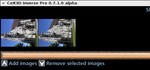
The Add images button is used when image files have been selected in the Files listbox, as described in the previous sections. Pressing the Add images button adds the selected images to the image sequence used for 3D reconstruction:
The added images will appear in the image sequence used for 3D reconstruction:
The following image formats are supported for input on Linux (via the SDL_image library): BMP, GIF, JPEG, LBM, PCX, PNG, PNM, TGA, TIFF, WEBP, XCF, XPM and XV. On Windows, however, only BMP format is currently supported; we expect this to improve one way or another in coming versions.
More images can be added by selecting other images, possibly from other directories, and pressing the Add images button again.
When the Add images button is pressed to add images and the
image sequence is empty, the directory that the images
are added from is automatically filled in as the
Output directory, in case the Output directory
specified at that time is an invalid path. If the
Output directory is already valid, it is not changed.
See the description of the reconstruction setting Output directory
for more information about Output directory.
Remove Selected Images
If too many or undesired images have been added to the image sequence, images can be removed by the Remove selected images button. First, select the image or images to remove from the image sequence:
When the Remove selected images button is pressed, the selected images are removed from the image sequence:
It is possible to select multiple images in the image sequence
by holding down CTRL or SHIFT and clicking the images with the mouse.
This is useful for removing multiple images at a time.
Suffle Left and Right
The order of the images in the image sequence is important for 3D reconstruction, at least in the current versions of CeX3D Inverse. Therefore, the image sequence may be reordered by using the Shuffle selected images buttons:
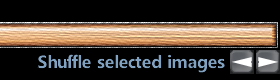
First, select the image or images to shuffle in the image sequence:
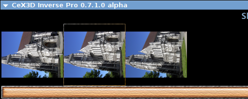
If the Shuffle selected images button with the right pointing arrow is pressed, the selected image or images are removed one image slot towards the right:
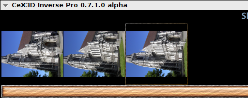
Pressing the Shuffle selected images button with the left pointing arrow shuffles one image slot towards the left.
It is possible to select multiple images in the image sequence
by holding down CTRL or SHIFT and clicking the images with the mouse.
This is useful for shuffling multiple images at a time.
Reconstruction Settings
The following sections list each of the reconstruction settings for
CeX3D Inverse. The settings are described
alphabetically according to their names.
Export Format: Wavefront OBJ
The export format setting 'Wavefront OBJ' specifies whether or not to export a reconstructed 3D model in Wavefront OBJ format. It may either be checked or unchecked. If checked, a 3D model is exported in OBJ format, otherwise it is not.

Whenever an OBJ file is generated, a corresponding .mtl file is also generated for specifying the texture of the object.
The Wavefront OBJ export format setting corresponds to the option '--exportObj' in the command line version of CeX3D Inverse.
CeX3D Inverse NCU has the limitation that a reconstructed
3D model may only be exported into one format each time
a 3D reconstruction is performed. The Wavefront OBJ format
is one such format. To export into multiple different formats
with CeX3D Inverse NCU, it is necessary to run the reconstruction
multiple times. With CeX3D Inverse Pro, any number of formats
may be exported for the same 3D reconstruction.
Export Format: RIB
The export format setting 'RIB' specifies whether or not to export a reconstructed 3D model in RenderMan RIB format. It may either be checked or unchecked. If checked, a 3D model is exported in RIB format, otherwise it is not. RenderMan is a registered trademark of Pixar Animation Studios.
Whenever a RIB file is generated, a corresponding .sl file, currently always named simpleUvTexture.sl, is also generated for specifying the texture of the object.
The RIB export format setting corresponds to the option '--exportRib' in the command line version of CeX3D Inverse.
CeX3D Inverse NCU has the limitation that a reconstructed
3D model may only be exported into one format each time
a 3D reconstruction is performed. The RenderMan RIB format
is one such format. To export into multiple different formats
with CeX3D Inverse NCU, it is necessary to run the reconstruction
multiple times. With CeX3D Inverse Pro, any number of formats
may be exported for the same 3D reconstruction.
Output Directory
When 3D reconstruction is performed, the generated models are placed in the directory specified for Output directory:
At the right side of the Output directory label, there is an indication of whether the entered value is valid or not. A blue check-mark is shown when it is valid or a red cross if invalid.
If the output directory is invalid when the first images are
added with the Add images button (see the File Browsing and Image Sequence
section), the directory that the
images are added from will be automatically filled in here.
Pixels per Point
CeX3D Inverse currently generates two different kinds of 3D model files: a low-resolution model whose file name normally starts with 'output_secondviewsheet_' and a high-resolution model whose file name normally starts with 'output_volume_'. Generating the high-resolution model is currently very resource intensive, taking time and using lots of memory, and it may fail. The resolution of the high-resolution model can be controlled by the setting Pixels per Point. Higher values give a lower resolution and generally requires fewer resources, is faster and more likely to succeed. Lower values give a higher resolution and requires more resources, especially if the input images have a high resolution. If your input images have a fairly low resolution (e.g. less than 1000x1000 pixels), it may be desirable to use a higher resolution, i.e. a lower value.
The setting Pixels per Point specifies roughly how many pixels in both height and width of a small square area are used in the final reconstruction for each point on the 3D model. Thus, when using a value of 4, an area of 4x4 pixels is used for roughly each point on the reconstructed 3D model. Hence, the resolution of the high-resolution model depends on both the setting Pixels per Point as well as the resolution of the input images. The default value for the setting Pixels per Point is 4. Supported values are currently 1, 2, 4, 8 and 16. An example is thus to specify 8:
The Pixels per Point setting corresponds to the option
'--pixelsPerPoint' in the command line version of CeX3D Inverse.
Radial Distortion Hint
Photographs taking with an ordinary camera normally have radial distortion due to the camera lens. CeX3D Inverse has to estimate this radial distortion. To help it in this estimation, you may provide a hint of the expected typical radial distortion in the images, which is done by specifying a value for the 'Radial Distortion Hint' setting. Supported values are in the range -0.25 to 0.25. Negative values correspond to a "barrel distortion", so named because when straight lines in the real world occur near the edges of the image with this distortion, those lines "bend outwards", similar to the silhouette of a barrel. Positive values correspond to a "pincushion distortion", where straight lines occurring near the edges of the image "bend inwards", similar to the edges of a pillow or a cushion. The value 0.0 is default and corresponds to no distortion. The values -0.25 and 0.25 are quite extreme distortion values and they are not likely to occur in practice for ordinary cameras and lenses. Fisheye lenses may come close to -0.25 or even lower but such extremes of lenses are currently not supported.
Cameras typically have a distortion that corresponds to a radial distortion hint of between -0.03 and 0.03. Hence, e.g. -0.02 could be a good hint value. This is specifed by entering -0.02 for Radial Distortion Hint:
The radial distortion, however, depend on which camera is used (particularly its lens), on how its zoom settings are as well as slightly on focus settings; using autofocus makes this somewhat uncontrollable. Typically, when the camera is zoomed out, the distortion is more negative, e.g. -0.02 or lower. When zooming in, the distortion gets closer to zero or even becomes positive, depending on the lens and camera. Currently, the most frequent point of failure in the reconstruction is the radial distortion estimation and for this reason, you may want to try the reconstruction with several different values for 'Radial Distortion Hint'. The actual estimated radial distortions are shown during reconstruction, which may give you an idea of how the actual radial distortion is, by comparing the estimated distortion values with the quality of the reconstructed 3D model: when you get a good 3D model, the estimated radial distortions are likely closer to the truth than when you get a bad model.
At the right side of the Radial distortion hint label, there is an indication of whether the entered value is valid or not. A blue check-mark is shown when it is valid or a red cross if invalid.
The Radial Distortion Hint setting corresponds to the option
'--radialDistortionHint' in the command line version of CeX3D Inverse.
Random Seed
Some of the algorithms in CeX3D Inverse are based on statistics and randomness. If the 3D reconstruction fails, it is likely that you have just been unlucky. You can change the randomness and try the reconstruction again by specifying a value for the 'Random Seed' setting. The default value is 2, so specifying a different value than the default, e.g. 3, is done by entering that value:
This option is also useful for scientific evaluation of the reconstructions. To make such an evaluation, multiple reconstructions from the same images and with the same parameters are typically made; each reconstruction should then be done with a different value of Random seed, in order to evaluate the average reconstruction quality and the robustness of this quality.
At the right side of the Random seed label, there is an indication of whether the entered value is valid or not. A blue check-mark is shown when it is valid or a red cross if invalid.
The Random seed setting corresponds to the option
'--randomSeed' in the command line version of CeX3D Inverse.
Showing License Information
The following sections describe how the End-User License Agreement
and licensee information may be displayed.
Show License
The button Show License may be pressed to show the End-User License Agreement:

The button Show Licensee may be pressed to show the user's license information for the software, which includes information like name, affiliation, address and the type and number of licenses:

Notice, though, that a short
summary of the license information is normally always shown
when starting a reconstruction.
![]() Modified: 2015-04-12
Modified: 2015-04-12
E-mail: Contact